
| Price | usd50$ |
| MOQ | 100 pcs |
| Delivery Time | 7-25 days after order confirm |
| Brand | TAC |
| Place of Origin | GUANGZHOU |
| Certification | UL |
| Model Number | 10S66A-1300W |
| Payment Terms | L/C, T/T |
| Supply Ability | 50000 per week |
| Cycle count capacity | 40000mAH | Place of Origin | GUANGZHOU |
| Pressure difference recovery | <500mV | Pressure differential protection | ≥800mV |
| Design capacity | 40000mAH | Model Number | 10S66A-1300W |
| Supply Ability | 50000 per week | Protection Plates | 10S66A-1300W |
| Certification | UL | Full charge voltage | >34.55V |
| Brand Name | TAC | Payment Terms | L/C, T/T |
| Price | usd50$ | Delivery Time | 7-25 days after order confirm |
| Consumption of current | ≤12mA | Minimum Order Quantity | 100 pcs |
| Full of voltage | 3635mV | Self-discharge rate | 1% / Day |
| Charging end current | 1800mA |
BMS-10S66A-1300W,monitor Voltage, current, protection plate working
1. Functional Features
High-integrated analog front-end Adjustable overcurrent protection
Isolation of the power supply circuit Has a variety of dormancy and awakening modes
Integrated serial port IC Low power consumption
High Voltage Accuracy (≤10mV) RS485 Communication
High Current Accuracy (≤2%@FS) Adjustable Parameter Settings
4-Way Battery Temperature Detection (≤2°C) Data Refresh Interval (Period) ≤ 2 Seconds
SOC Estimation Function LED Status Indication Function
SOH Estimation Function Charge Equalization Function
Short Circuit Protection Function SOC Accuracy (≤5% @ 50% Capacity Range Or More)
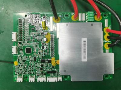
2. PCB diagram

3. Environmental Requirements
| Projects | Parameters | Unit |
| Operating Temperature | -20 to 70 | ℃ |
| Storage Temperature | -40 to 75 | ℃ |
| Operating Humidity | ≤95 (45°C±2°C) | %RH |
| Storage Humidity | ≤95 (45°C±2°C) | %RH |
| Temperature Measurement | -40 to 125 | ℃ |
| Atmospheric Pressure | 70~106 | kPa |
4. Interface definition

5.Note for installing the protective plate
1) First
connect
the
communication
port
CN1
or
CN3
according
to
the
wiring
diagram
of
the
protection
board;
2)
Connect
the
total
negative
electrode
of
the
cell
to
the
B-of
the
protection
plate;
3) Connect
the
total
positive
electrode
of
the
cell
to
the
B
+
terminal
of
the
protection
plate;
4) Connect
the
cell
B0.B2.B4.B6.B8.B10
to
the
protection
board
J4;
5)
Connect
the
cell
B1.B3.B5.B7.B9
to
the
protection
board
J3;
6) The
negative
of
the
load
/
charger
is
directly
connected
to
the
positive
electrode
of
the
protection
plate
P-;
8) The
positive
electrode
of
the
load
/
charger
is
directly
connected
to
the
positive
electrode
P
+
of
the
protection
plate;
9)
Charging
activation
/
communication
activation
/
button
activation;
6.Step
of
removing
the
protective
plate:
1)Remove
the
communication
port
CN1
or
CN3;
2)Remove
the
connection
line
of
the
P
+
load
/
charger
positive
electrode
on
the
protection
plate;
3) Remove
the
connection
cable
of
the
P-load
/
charger
anode
on
the
protection
board;
4) Remove
the
cell
B10.B9.B8.B7.B6.B5.B4.B3.B2.B1.B0
on
the
protective
plate
in
sequence;
5) Remove
the
total
positive
B
+
connection
line
of
the
cell;
6) Finally,
remove
the
connecting
line
of
the
total
negative
B-of
the
cell.