| Price | 715-4286 usd |
| MOQ | 1 set |
| Delivery Time | 15-20 working days |
| Brand | ESTEL |
| Place of Origin | Shenzhen, China (Mainland) |
| Certification | ISO9001, CE, 3C, FCC, TLC |
| Model Number | ETP48300 |
| Packaging Details | Wooden case |
| Payment Terms | L/C, D/A, D/P, MoneyGram, T/T |
| Supply Ability | 3,000 sets per month |
| Place of Origin | Shenzhen, China (Mainland) | Packaging Details | Wooden case |
| Installation Mode | 19 inch rack | Model Number | ETP48300 |
| Controller | Ethernet , SNMP, ModBus and RS485 communication | Supply Ability | 3,000 sets per month |
| Certification | ISO9001, CE, 3C, FCC, TLC | Name | Rack Mount Telecom Rectifier |
| Brand Name | ESTEL | Payment Terms | L/C, D/A, D/P, MoneyGram, T/T |
| Rectifier Module | 3KW×6pcs | Full Capacity | 300A |
| Price | 715-4286 usd | Delivery Time | 15-20 working days |
| Output voltage | DC48V | Minimum Order Quantity | 1 set |
| Battery Management | Support | Module | Hot-swappable |
| Output Voltage | -48VDC (-42 to -58VDC) | Application | telecom,utility,Industrial Automation,Electric Power Transmission,BTS |
9U Large Capacity Embedded Power Supply Standard 19-inch Rack or Built-in Cabinet
1. 9U Large Capacity Embedded Power Supply Features
DC Rectifier System supply 9U height compact design to meet critic
alapplication needs of fiber and microwave transmission, access device,
switch. The system maximum power is 300A, with customized AC/battery/load MCBs.
The cables are front accessing with MCB and busbar
2. 9U Telecom Power Supply Parameter
| Model | ETP48300 | |
| System | Dimension(mm) | 482.6(W)x350.6(D)x9U(H) |
| Weight | ≤ 50kg(without rectifier module) | |
| Cooling mode | Forced air cooling | |
| Installation mode | Installed on 19-inch rack or inside the cabinet | |
| IP Grade | IP20 | |
| AC Distribution | Input voltage |
380VAC, three phase |
| Input capacity | 2x63A/4P | |
| Input frequency | 45~65Hz, rated 50/60Hz | |
| AC SPD | 20kA/30kA, 8/20μs | |
|
DC Distribution |
Output voltage | -42~-58VDC, rated value: -53.5VDC |
| Maximum capacity | 18kW(6x3000W rectifier module) | |
| Battery breakers |
2x125A/1P |
|
| Load breakers |
User 1: LLVD1: 1×125A/1P, 1×63A/1P, 1×16A/1P, 1×6A/1P; BLVD1: 1×63A/1P; User 2: LLVD2: 1×63A/1P, 2×16A/1P, 1×6A/1P; BLVD2: 1×63A/1P; User 3: LLVD3: 1×63A/1P, 2×16A/1P, 1×6A/1P; BLVD3: 1×63A/1P; User 4: LLVD4: 1×63A/1P; BLVD4: 3×10A/1P; |
|
| DC SPD | 10kA/20kA, 8/20μs(designed inside) | |
| Rectifier Module | Input voltage | 85VAC-300VAC, rated value: 220VAC |
| Efficiency | ≥96% | |
| Rated power | 3000W(176~300VAC ) | |
| Dimension | 106.5mm(W)×286mm(D)×41.5mm(1U/H) | |
| Cooling mode | Forced cooling with fan | |
| Controller | Signal input | 3 AI(2 battery temp., 1 ambient temp) ,7 DI(SPD, 6 common DI) |
| Alarm output | 6 dry contact | |
| Communication port | RS485/LAN Ethernet/SNMP | |
| Display mode | LCD | |
|
Environment |
Operating temperature |
-40℃~+65℃ |
| Storage temperature | -40℃~+70℃ | |
| Operating humidity | 5%~95%(non-condensing) | |
| Altitude | 0~3000m(If the altitude is within the range of 2000m to 3000m, the maximum operating temperature decreases by 1℃ as the altitude increases by 200m.) | |
3. ESTEL 48v Telecom Power Supply
A
rectifier
converts
alternating
current
(AC)
to
direct
current
(DC)
and
provides
the
power
necessary
to
charge
batteries.
With
a
focus
on
continuously
improving
the
total
cost
of
ownership,
ESTEL’s
rectifiers,
combined
with
advanced
control
and
monitoring
features,
help
reduce
both
capital
and
operational
expenditure.
Our
rectifiers
boast
excellent
power
density
while
fulfilling
space
and
weight
requirements.
They
leave
plenty
of
room
for
other
equipment
and
create
savings
in
packaging
and
transportation
costs.
In
addition,
their
high
efficiency
lowers
total
energy
consumption
and
reduces
carbon
footprint.
ESTEL’s
rectifiers
are
easy
to
install,
as
their
connectors
are
located
at
the
rear
and
are
hot-pluggable.
Fan
cooling
with
speed
control
renders
operating
almost
silent.
In
general
the
rectifiers
include
a
wide
AC
input
voltage
range,
protection
against
AC
overvoltage
and
optional
protection
against
loss
of
neutral,
which
make
this
solution
very
reliable
even
in
the
regions
with
AC
utility
network
problems.
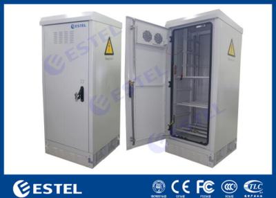
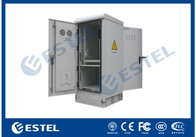
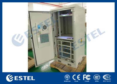
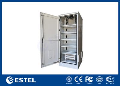
4. Product Pictures

Rack mounted pictures for reference:

5. Controller-MC2600 (Monitoring Module)
The MC2600 front panel


(1) LAN port (2) RS485 port (3) Run indicator (4) Minor alarm indicator
(5) Major alarm indicator (6) Handle (7) Buttons
Table for controller button description
| Button | Description | |
| ESC |
Returns to the previous menu without saving the settings. |
Press the ESC and ENT button at the same time within a short period of time can restart the controller. |
|
ENT.
|
Ø Enters the main menu from the standby screen. Ø Enters a submenu from the main menu. Ø Saves the menu settings. |
|
| UP |
Turns to the previous menu or sets parameter values. When setting parameter values, you can hold down this button to quickly adjust values. |
When the parameter value is set by multiple string types, press up or down button to change each value. After setting the value, press the confirm button to move the cursor back automatically. |
| DN. |
Turns to the next menu or sets parameter values.When setting parameter values, you can hold down this button to quickly adjust values. |
|
Describes the indicator on the controller panel is shown in table below
| Type | Color | State | Instructions |
| Run indicator | Green | Flickering | Controller is running properly |
| Off | Controller is fault or has no DC input | ||
| Minor Alarm | Yellow | Normally on | The controller generates a minor alarm |
| Off | The controller does not generate any minor alarms | ||
| Major alarm | Red | Normally on | The controller generates a major alarm |
| Off | The controller does not generate any major alarms |
The controller provides two communication ports
The definition of RS485 communication port is shown in below table
| Pin No. | 1 | 2 | 3 | 4 | 5 | 6 | 7 | 8 |
| Signal name | RS485+ | - | RS485- | - | - | - | - | - |
The LAN Ethernet port interface definition is shown in Table
| Pin No. | 1 | 2 | 3 | 4 | 5 | 6 | 7 | 8 |
| Signal name | TX+ | TX- | RX+ | - | - | RX- | - | - |
6. Subrack Installation
Install the subrack to the 19-inch rack, as shown in Figure below.
Ø Step 1,Remove the plug from the package.
Ø Step 2,Push the plug into the 19-inch rack
Ø Step 3,Install the fixed screw (if the mounting hole of the plug frame ear does not correspond to the position of the floating nut of the frame,
it needs to be adjusted according to the actual installation).

Install Rectifier/Solar module
Ø Step 1, Take out the module from the package.
Ø Step 2, Hold the module handle on the front panel and put the module onto the slot.
Ø Step 3, Push the module slowly to the front panel of the module and flush with the power
distribution panel.
Ø Step 4, Tighten the fixing screw on the module panel so that the module does not come off.