GXCM07-12
PROPELLER
TYPE
CURRENT
METER
1.
Description
GXCM07-12
Propeller
Type
Current
Meter
is
used
to
measure
hourly
average
flow
velocity
on
given
points.
Being
light,
impact
and
portable,
this
instrument
applies
to
rivers,
pipelines,
irrigation
and
drainage
channels,
hydrological
investigation,
and
runoff
experiments.
2.
Specification
|
The
Rotary
Diameter
for
Propeller
|
Ф60mm
|
|
The
Hydraulic
Thread
Pitch
for
Propeller
|
H=120mm
|
|
Minimum
Velocity
|
Vo≤0.06m/s(Normal)
Vo≤0.05m/s(Premium)
|
|
Operational
Depth
|
0.1~1.2m(Wading
rod)
|
|
Accurancy
|
unbiased
variance:
m≤±1.2%(Normal)
m≤±1.0%(Premium)
V<0.2m/s
Relative
Error:σ≤±5%
|
|
Signal
|
two
signals
on
every
rotary
|
|
Operational
Condition
|
0~35℃
|
|
Continuous
Running
Time
|
24h
|
|
Wading
Rod
(additional)
|
CG16-1
wading
rod
for
open
channel:
1600
mm
in
four
sections;
Inner
supporting
type
special
wading
rod
for
pipeline
|
3.
Configuration
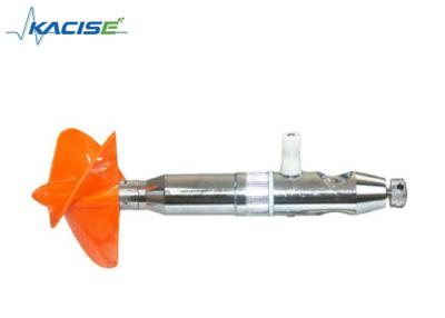
1)
GXCM07-12
Propeller
Type
Current
Meter
is
composed
of
a
sensing
part,
signal
transition
mechanism,
a
tail
fin,
and
a
wading
rod.
Instruction
of
counter
is
in
last
page
of
the
text.
2)
Sensing
Part
Installed
on
the
rotary
axis
at
the
front
part
of
the
instrument,
the
sensing
part
is
a
three-leaf
screw
propeller
used
to
sense
the
flow
velocity.
Rotate
speed
of
the
propeller
is
proportional
to
flow
rate.
The
proportional
constants
are
measured
in
flume
testing.
3)
Signal
Transition
Mechanism
Signal
transition
mechanism
is
to
transform
rotating
number
of
propeller
into
electrical
pulse
signals
for
counting
by
magnet—reed
switch.
Magnet
is
vertically
installed
at
the
tail
of
the
rotary
axis,
synchronous
rotating
with
propeller.
Reed
switch
is
encapsulated
in
a
water-proof
component
fixed
on
the
main
body
close
to
magnet.
When
propeller
is
driven
by
current,
magnet
and
propeller
are
rotating
synchronously.
Every
propeller’s
rotation
induces
two
times
of
magnetization
between
magnet
and
reed
switch.
The
rotating
number
is
transformed
into
signals
and
transmitted
to
the
counter.
4)
Tail
Fin(Additional)
Tail
fin
is
used
to
level
instrument
in
open
channel
during
flow
measurement.
If
in
shallow,
and
slow-rate
flow,
or
pipelines,
instruments
can
be
leveled
by
eyeballing,
tail
fins
are
not
necessary.
5)
CG16-1
Type
Wading
Rod(Additional)
Wading
Rod
is
used
to
measure
water
depth,
and
fixed
instrument
at
the
given
measuring
points.
There
is
a
signal
transition
socket
on
top
of
the
wading.
4.
Operational
Principles
and
Calculation
The
functional
relationship
between
flow
rate
and
rotary
speed
of
propeller
is
determined
by
flume
testing.
Calibration
formula:
V
=
Kn
+
C
V—flow
rate,m/s;
K—hydraulic
thread
pitch
of
propeller,m;
n—rotary
rate
of
propeller,n=
N
/T,1/s
(
N—rotating
number
of
propeller;
T—measuring
duration);
C—instrument
constant,m/s.
Flow
rate
actually
is
average
rotary
rate
of
propeller
in
given
measuring
duration.
5.
Maintenance
Propeller
The
material
of
the
propeller
is
excellent
engineering
plastic.
After
more
than
ten
years
of
various
experiments,
this
material
is
proved
to
be
characteristic
of
impact-resistance,
corrosion-resistance,
atmosphere-caused
deterioration-resistance
and
good
thermal
stability,
up
to
technical
standards.
Quality
of
Propeller
dominates
the
capability
of
the
instrument.
In
order
to
guarantee
accurate
value
of
K
in
above
formula,
maintenance
of
propeller
should
be
emphasized.
1)
Prevent
it
from
fierce
impact
during
measurement.
2)
Clean
out
oil
and
sediment
from
propeller
by
water
or
gas,
keeping
it
clean
and
dry.
3)
In
ice
seasons,
boiled
water
can
be
poured
on
propeller
to
thaw
the
ice.
Never
use
fire
to
roast
it.
4)
Propeller
is
fixed
on
rotary
axis
by
screw
threads.
If
under
fast
flow
rate,
hook
spanner
should
be
used
to
screw
it
down.
Especially
for
measurement
in
pipelines
of
pumping
stations,
when
measurement
instantly
finishes,
reverse
current
will
make
the
propeller
rotate
rightabout.
Screw
thread
is
easy
to
loose.
Never
use
wire
cutter
to
screw
it
down
for
fear
of
laceration.
Ball
Bearing
As
a
crucial
component
of
the
supporting
system
of
the
current
meter,
the
ball
bearing,
especially
the
low-rate
section
influences
the
capacity
of
the
instrument.
Technical
schedule
should
be
conformed
to
cleanse
the
ball
bearing.
Material
of
ball
bearing
is
9Cr18
stainless
steel.
Although
it
is
rust-resistant,
careful
maintenance
for
GCr15
stainless
steel
should
be
conducted
on
it.
If
damaged,
the
ball
bearing
can
be
purchased
according
to
code:
D25MX.
Cleansing
the
ball
bearing:
1)
Gas
Number
120(SY1207—67)
or
Number
200(GB444—64)
is
good
cleanser.
2)
Cleansing
should
be
conducted
in
a
covered
porcelain
box
or
aluminum
mess
tin.
Set
a
copper
screen
(65
eyes/3.3cm)
at
10mm
from
box
bottom
to
filter
the
sediment.
Prepare
three
boxes
for
rough
cleansing
and
finish
cleansing.
3)
Operators
should
wash
hands
with
warm
water
and
soap.
Other
people
must
not
touch
the
ball
bearing
by
hand.
4)
The
ball
bearing
chamber
should
be
cleansed
carefully
to
prevent
dust,
the
archenemy
for
ball
bearing.
5)
GB487—84
Instrument
oil
is
6.3—8.5
centistroke
at
50℃.
It
has
excellent
viscosity-temperature
characteristics
and
lean
harmful
substances
such
as
acid,
moisture,
dust
and
mechanical
impurity,
up
to
strict
standards.
If
other
types
of
instrument
oil
are
used,
new
calibration
on
it
should
be
made.
6)
Cleanser
and
instrument
oil
should
accord
with
international
standards,
properly
deposited,
and
strictly
prevented
from
water
and
impurity.
7)
Cleansing
Procedure
Rotate
and
clean
the
ball
bearing
in
first
box
with
gas
10
times,
half
in
one
direction.
Then
turn
to
the
second
and
third
boxes
to
repeat
the
same
process.
Shake
off
gas,
and
install
the
ball
bearing
instantly,avoiding
long-time
exposure
in
air.
If
there
is
any
water
entering
into
the
ball
bearing
chamber
(judged
by
sensitivity
of
propeller’s
rotation)
after
measurement,
clean
it
in
time.
Hold
the
circular
circumference
of
ball
bearing,
shaking
the
water
or
sediment
out
of
the
ball
bearing
in
axial
direction.
Then
repeat
the
cleansing
procedure
in
(7).
8)
Keep
the
instrument
in
airy,
dry
and
noncorrosive
room.
After
3
–6
months,
ball
bearing
should
be
checked,
cleaned,
and
oiled.
Dismantling,
Washing,
Assembling
and
Oil
Filling
Although
the
bearing
chamber
and
the
rotary
axis
have
excellent
sealing
performance,
sordid
condition
and
ignorance
of
technical
principles
will
induce
moisture
entering
into
the
chamber.
Special
attention
must
be
paid
during
dismantling,
washing,
assembling
and
oiling
the
instrument.
(1)
Dismantling
and
Washing
After
measurement,
dismantle
the
current
meter
body
from
the
bracket.
Check
the
quality
of
oil
in
bearing
chamber
from
transparent
cap.
If
the
oil
is
clear
without
water
in
it,
and
sensibility
of
propeller
is
normal,
the
instrument
is
not
requisite
to
be
washed.
However,
in
order
to
guarantee
the
accuracy
of
the
instrument,
open
the
transparent
cap,
add
oil
into
the
bearing
chamber
and
squeeze
out
the
water
drops
from
the
front
part.
If
the
oil
in
bearing
chamber
is
a
little
feculent,
the
instrument
should
be
dismantled
completely.
(2)Assembling
According
to
reverse
sequence
of
dismantling,
assemble
the
components
washed.
Tighten
the
screw
caps
by
hand
or
hook
spanner.
Assembling
should
be
checked
as
followed.
1)
The
assemblage
gap
between
propeller’s
rotary
set
and
main
body
of
the
instrument
is
0.3—0.4mm
which
can
be
measured
by
thickness
gauge.
If
the
gap
is
too
narrow,
a
gasket
can
be
added
to
the
tread
of
rotary
set
to
avoid
the
friction
possible
to
influence
sensibility
of
the
instrument.
If
the
gap
is
too
wide,
water
is
easy
to
enter
into
the
bearing
chamber.
The
two
abnormal
situations
are
mainly
caused
by
nonstandard
assembling
procedure.
2)
The
bounce
gap
of
rotary
set
should
not
surpass
0.03mm
checked
by
dial
gauge.
Dial
the
propeller
by
hand.
If
rotation
of
propeller
is
not
so
smooth
but
a
little
shaky,
it
is
not
accordant
with
standards.
Check
the
bounce
gap
of
propeller
axis
and
rotary
set
by
dial
gauge
to
determine
repair
methods.
Special
notice:
extrusion
of
eccentric
driven
pump
is
most
possible
to
cause
water
intake.
3)
Sensibility
of
the
instrument
is
checked
by
mouth’s
blowing.
If
a
slight
blowing
drives
the
propeller
rotate
smoothly
without
sense
of
blocking,
the
sensibility
is
considered
to
be
eligible.
We
recommend
JGM-1
type
flywheel
sensibility
checking-gauge
developed
by
our
institute.
The
flywheel
is
working
with
a
suspended
cable
and
a
weight.
Average
moment
of
friction
is
determined
by
rotation
duration
of
the
flywheel.
Thus,
sensibility
of
the
instrument
can
be
judged.
It
is
more
reliable
to
use
the
gauge
to
measure
sensibility.
4)
The
instrument
assembled
should
be
placed
on
table.
Lay
wood
block
under
the
body,
keeping
the
propeller
suspending.
Otherwise,
put
it
into
housing
immediately.
(3)
Oil
Filling
Bearing
and
distance
sleeves
are
washed,
then
assembled
together.
If
the
rotary
set
is
proved
to
be
accordant
with
technical
demands,
fill
oil
in
the
chamber
assembled
with
rotary
set,
and
the
cap.
Couple
them
together
instantly
and
tighten
the
cap.
If
the
instrument
oil
throws
from
the
rotary
set
and
there
is
no
air
bubble
in
the
cap,
the
chamber
must
be
filled
up.
In
order
to
prevent
chamber
from
air
bubbles,
keep
the
head
of
instrument
on
the
top
when
you
tighten
the
cap.
Fill
oil
in
holes
of
bracket,
then
assemble
it
with
the
main
body.
Thus,
the
instrument
is
full
of
oil
inside.
Signal
Transition
Mechanism
Signal
transition
mechanism
is
composed
of
magnet
and
reed
switch.
The
magnet
is
hold
in
the
magnet
box.
Remanence
is
700—1000Gauss.
The
reed
switch
is
sealed
with
epoxy.
The
minimum
ampere-turns
is
12—18AT.
The
magnet
and
reed
switch
on
one
instrument
are
not
exclusively
coupled,
but
exchangeable
with
other
instruments.
They
are
also
disposable
an
purchasable.
Life
span
of
reed
switch
is
greatly
influenced
by
power
system
load.
At
3V
and
30mA,
it
can
work
5×10⁵times.
After
that
it
should
be
replaced.
1minute
is
only
needed
for
replacement,
even
in
field.
It’s
not
necessary
to
lift
the
instrument
up
from
water,
because
reed
switch
is
completely
sealed.
Notice
the
value
of
power
and
current
of
the
counter
connected.
Never
choose
inductance
type
counter.
In
water
with
high
salinity
or
industrial
polluted
wastewater,
such
as
electroplating
effluent,
Adhesive
plaster
can
be
used
to
wrap
the
binding
posts
(positive)
of
reed
switch,
avoiding
short
circuit
with
main
body
of
the
instrument
(negative)
in
water.
Incasement
After
measurement,
lift
the
instrument
up
from
water.
Dry
it
with
towels.
Put
it
into
housing
according
to
original
position.
Other
accessories
should
be
well
placed.
Check
the
placement
of
components
if
the
housing
can’t
be
well-covered.
Never
forcedly
press
the
cover
of
housing.
6.
Complete
set
|
Item
|
Number
|
|
Main
body
(with
screws
used
to
fix
main
body
on
wading
rod)
|
1
|
|
Spare
reed
switch
(with
cap
to
contain
line)
|
1
|
|
Adjusting
pin
|
2
|
|
Oil
bottle
|
1
|
|
coefficient
card
|
1
|
7.
Life
Span
1.
5years
under
correct
operation
and
maintenance.
2.
Under
correct
operation,
calibration
formula
should
be
checked
after
1—2years.