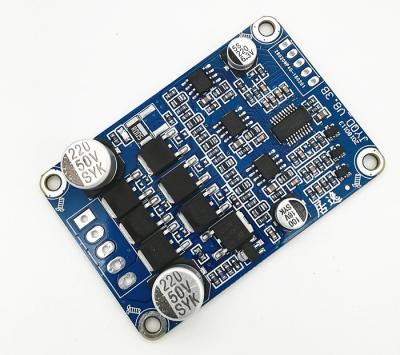
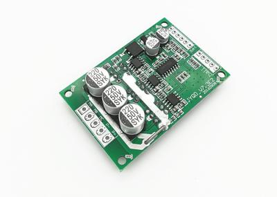
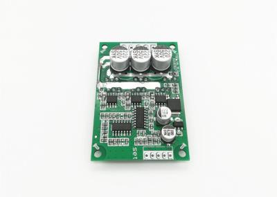
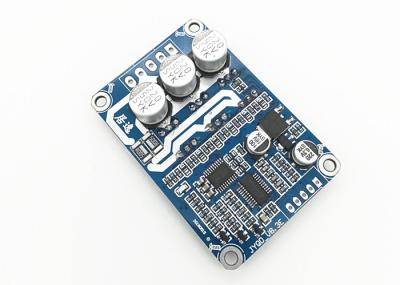
1.Control
port
(SET)
Z/F----
Rotating
direction
control
ports.
Connect
“5V”
or
no
connect
is
Forward
direction,
connect
to
GND
is
reverse
direction.
EL
----
Enable
control
port.Connect
“5V”or
no
connect
is
running
status,
connect
to
GND
is
Stop.
BK
---
Brake
control
port.
Connect
“5V”or
no
connect
is
running
status,
connect
to
GND
is
braking.
VR
----Speed
control
port.
Analog
voltage
linear
speed
regulation
0.1v
-5V,
The
input
resistance
is
20K
Ohm
,connect
with
GND
when
input
PWM
speed
regulation,
PWM
frequency:1-20KHZ;
Duty
cycle
0-100%
FG
---
Motor
speed
pulse
output
signal,
output
current
less
than
5mA.
GND—
Used
for
Drive
board
internal
control.
ALM
---
Running
indication.
the
motor
outputs
high
level
(5V)
normally
when
it
is
running,
and
outputs
low
level
(0V)
when
the
motor
runs
abnormally,
and
the
current
is
less
than
5Ma.
5V
-----
Driver
board
internal
output
voltage.Only
power
potentiometer,
switch
speed
regulation
and
reversal
use
(external
electrical
equipment
is
prohibited).
2.
Hall
port
HA
----
Hall
A
HB
----
Hall
B
HC
----
Hall
C
GND
----
Motor
Hall
Signal
Negative
power
port
5V
----
Motor
Hall
Signal
Positive
power
port
3.
Power
port
P+
---
DC+
P-
---
DC-
U
---
Motor
phase
line
V
---
Motor
phase
line
W
---
Motor
phase
line
4.Pay
attention
to
the
motor
line
is
not
too
long,
the
drive
board
is
dependent
on
the
anti-electromotive
force
detection,
the
line
is
too
long
will
appear
signal
interference
5.Control
port
distance:
2.54mm,Power
port
distance:3.96
mm
6.When
the
driving
power
is
large,
forced
heat
dissipation
measures
should
be
taken
to
prevent
excessive
temperature
of
the
controller
from
affecting
normal
use.


