| Price | Negotiable |
| MOQ | 1 set |
| Delivery Time | 5-8 working days |
| Brand | JUYI |
| Place of Origin | China |
| Model Number | JYQD-YL01D |
| Packaging Details | PE bag+ carton |
| Payment Terms | L/C, T/T,Paypal |
| Supply Ability | 1000sets/day |
| Place of Origin | China | Commutation | Brushless |
| Packaging Details | PE bag+ carton | Color | Green |
| Pwm Speed Control | Duty cycle 0-100% | Model Number | JYQD-YL01D |
| Supply Ability | 1000sets/day | Voltage Range | 12-48VDC |
| Brand Name | JUYI | Payment Terms | L/C, T/T,Paypal |
| Type | Brushless DC Motor | Price | Negotiable |
| Delivery Time | 5-8 working days | Minimum Order Quantity | 1 set |
| Working Temperature | -20℃—85℃ | Motor Type | DC Brushless 3 Phase |
| Rated Current | 15A | Speed Control | PWM or 0-5V |
| Application | Remote-controlled electric vehicles |
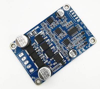
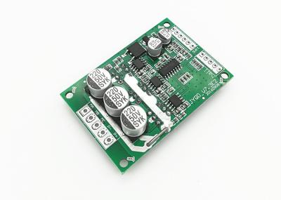
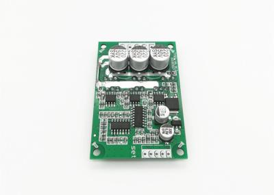
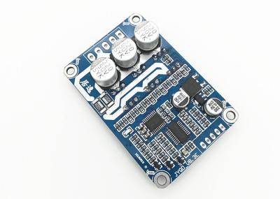
JUYI Energy-Efficient BLDC Motor Driver Board 12V 24V 48V with Brake Function
|
Model
|
JYQD-YL01D
(8559)
|
JYQD-YL01D
(457E)
|
JYQD-YL01D
(99F2)
|
JYQD-YL01D
(C737)
|
|
Working
Temperature(℃)
|
-20—85
|
-20—85
|
-20—85
|
-20—85
|
| Working Voltage(V) |
12V-48V
|
12V-48V
|
12V-48V
|
12V-48V
|
|
Max.operating
current(A)
|
15A
|
15A
|
15A
|
15A
|
|
PWM
speed
control
PWM
frequency(1-
20KHZ)
|
Duty
cycle
0-
100%
|
Duty
cycle
0-
100%
|
Duty
cycle
0-
100%
|
Duty
cycle
0-
100%
|
|
Analog
voltage
speed
regulation(V)
|
0-5V
|
0-2.5V
|
0-5V
|
0-2.5V
|
| Liner brake (V) | 0-5V |
0-2.5V
|
0-5V |
0-2.5V
|
|
Speed
pluse
signal
output
|
√
|
√
|
√
|
√
|
| Reversing function |
√
|
√
|
√
|
√
|
| Safe start function |
X
|
X
|
√
|
√
|
Application Fields
Remote-controlled
electric
vehicles,
self-balancing
scooters,
remote-controlled
wheelchairs,
medical
robots,
recreational
vehicles,
robotics,
etc.
Application
Guidelines
1.
Confirm
the
motor's
voltage
and
power
parameters.
Do
not
exceed
the
specifications
of
the
driver
board.
2. The driver board is compatible with Hall-type three-phase brushless DC motors, but not all such motors can be used directly. Ensure the motor's Hall sensor angle is 120 degrees.
3. The JYQD_YL01D braking function is regenerative braking. Rotating motors during braking generate recoverable energy. Do not test the braking function with a regulated power supply, as this may cause damage.
4. The 5V output port on the driver board can provide <100mA current for microcontroller control.
5. Ensure proper insulation and heat dissipation for power components on the driver board during operation.
6. Safety startup function: After power-on, speed adjustment will be disabled until reset. To resolve, perform either a speed reset or brake reset.
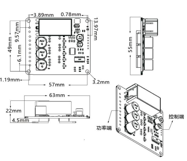
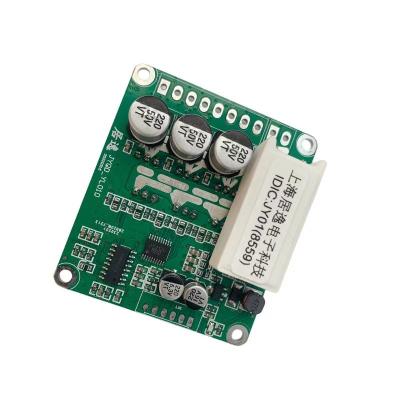
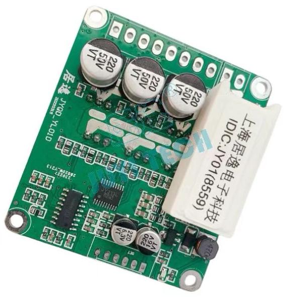
Product diagram

Wiring Diagram

I.
Control
Port
(Right
Side)
|
2.54mm
Pitch
1.
5V –
Internal
5V
output
from
control
board.
2. EL – Brake control port with reactive linear braking and energy recovery. Analog voltage braking range 0-5V: Higher voltage under constant RPM increases braking force (0-100% linear scaling).
3. M – RPM signal output port. Pulse frequency proportional to motor speed (pulse ratio varies by motor model).
4.
Z/F –
Forward/reverse
control
port.
Hard
commutation
logic:
-
Connect
to
5V
or
leave
floating
→
clockwise
rotation
-
Connect
to
GND
→
counterclockwise
rotation
5.
VR –
Speed
control
port.
Analog
voltage
regulation:
-
0-5V
(effective
range
0-2.5V)
for
linear
speed
scaling
(low
to
high)
-
Requires
common
ground
with
driver
board
for
external
PWM
input
6.
GND –
Control
board
internal
ground.
II.
Power
Port
(Left
Side)
|
3.96mm
Pitch
1.
P+ –
DC
power
input
positive
(12V-48V,
supports
lithium
batteries)
2. P- – DC power input negative
3. MC/W – Motor phase wire W
4. MB/V – Motor phase wire V
5. MA/U – Motor phase wire U
6. GND – Hall sensor ground
7. HA/HB/HC – Hall sensor signal outputs
8.
5V –
Hall
sensor
power
supply
III.
Critical
Notes
1.
Cable
Length –
Motor
wires
should
not
too
long
to
prevent
signal
interference.
2.
Thermal
Management –
For
continuous
high-current
operation
: When
working
with
continuous
high
current,
attention
should
be
paid
to
heat
dissipation
IV.
Safety
Compliance
-
Do
not
reverse-polarity
connect
P+/P-
-
Verify
insulation
resistance
(>10MΩ)
between
power
and
control
ports
Dimensional Drawing