| Price | negotiable |
| MOQ | 1 set |
| Delivery Time | Negotiable |
| Brand | JUYI |
| Place of Origin | China Mainland |
| Model Number | JYQD-V7.3E2 |
| Packaging Details | PE bag+ carton |
| Payment Terms | T/T,Paypal |
| Supply Ability | 1000 sets/day |
| Place of Origin | China Mainland | Commutation | Brushless |
| Packaging Details | PE bag+ carton | Color | Green |
| Model Number | JYQD-V7.3E2 | Supply Ability | 1000 sets/day |
| Hall Sensor Angle | 120 degree | Working Temp | -20-85 degrees |
| Brand Name | JUYI | Payment Terms | T/T,Paypal |
| Price | negotiable | Minimum Order Quantity | 1 set |
| Max Drive Power | 500W | Maximum Current | 16A |
| Cooling Mode | Natural or forced cooling | Current | 15A |

Application Instructions:
1. Confirm the voltage and power parameters of the motor, which must not exceed the range specified by this drive board.
2. This drive board is suitable for 120-degree Hall-effect DC brushless motors. Note that the wiring sequences of motors
from different manufacturers may not directly correspond to the drive board’s wiring sequence. Customers can adjust the
Hall wiring sequence or the three-phase motor wire sequence according to actual conditions to achieve optimal driving
performance (adjustment instructions are provided in the attached documents).
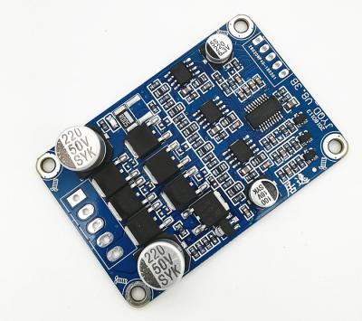
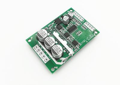
3. The JYQD_V7.3E2 drive board is a bare board. For motors with a power rating below 100W, forced cooling is not required,
but normal ventilation must be ensured.
4. The 5V output port on the drive board is prohibited from connecting external electrical devices. It is only suitable for
connecting external potentiometers and switches on the board for speed regulation and direction change.
5. The "Signa" port on the JYQD_V7.3E2 drive board is the motor speed pulse output signal, with an output current of less
than 5mA.

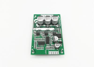
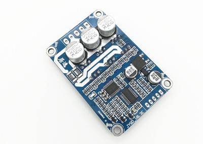
Diagram Without Heatsink Diagram With Heatsink
WIRING DIAGRAM:

1.
Hall
Port
(Top
Left)
GND
—
Hall
Signal
Negative
Interface
Hc
—
Hall
Signal
Hc
Hb
—
Hall
Signal
Hb
Ha
—
Hall
Signal
Ha
5V
—
Hall
Signal
Positive
Interface
2.
Control
Port
(Bottom
Left)
GND
—
Internal
Control
Ground
of
the
Drive
Board.
VR
—
Speed
Control
Port.
Analog
voltage
speed
regulation
(0V-5V),
linear
speed
adjustment
from
low
to
high.
PWM
speed
regulation
requires
common
ground
with
the
drive
board.
Z/F
—
Forward/Reverse
Control
Port.
Connect
to
5V
or
leave
floating
for
one
direction,
connect
to
GND
for
the
opposite
direction.
Signal
—
Motor
Speed
Pulse
Signal
Output
Port,
5V
pulse
signal.
EL
—
Enable
Control.
Connect
to
5V
to
allow
operation,
connect
to
GND
to
disable
operation.
5V
—
Internal
5V
output
of
the
control
board,
only
for
powering
potentiometers
and
switches
for
speed
regulation
and direction change.
3.
Power
Port
(Right)
VCC
—
DC
Power
Positive
(+)
GND
—
DC
Power
Negative
(-)
MC
—
One
of
the
Motor
Three-Phase
Wires
MB
—
One
of
the
Motor
Three-Phase
Wires
MA
—
One
of
the
Motor
Three-Phase
Wires
4.
Note:
Motor
phase
wires
and
Hall
wires
should
not
be
too
long,
as
excessive
length
may
cause
signal
interference
issues.
5.
Control
port
uses
a
2.54mm
pitch,
while
the
power
port
uses
a
3.96mm
pitch.
6.
When
adding
a
heat
sink
or
installing
the
board,
pay
attention
to
the
insulation
of
the
drive
board's
power
transistors.
Dimension Drawing: