| Price | negotiable |
| MOQ | 1 set |
| Delivery Time | 5-8 working days |
| Brand | JUYI |
| Place of Origin | China Mainland |
| Certification | ISO9001 |
| Model Number | JYQD-V7.3E2 |
| Packaging Details | PE bag+ carton |
| Payment Terms | Paypal,L/C,T/T |
| Supply Ability | 1000 sets/day |
| Place of Origin | China Mainland | Phase | 3 |
| Applications | Motor drive for 12V-36V Systems | Packaging Details | PE bag+ carton |
| Reversing Function | Yes | Model Number | JYQD-V7.3E2 |
| Maxumum Current | 15A | Supply Ability | 1000 sets/day |
| Operating Temp | -20-+85℃ | Certification | ISO9001 |
| Colour | Green | Brand Name | JUYI |
| Payment Terms | Paypal,L/C,T/T | Maximum Power | 500W |
| Price | negotiable | Delivery Time | 5-8 working days |
| Minimum Order Quantity | 1 set | Rated Current | 15A |
| Compatibility | Hall snesor | Suitability | Hall Sensor Motor |
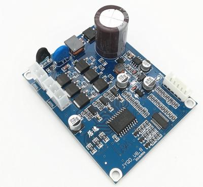
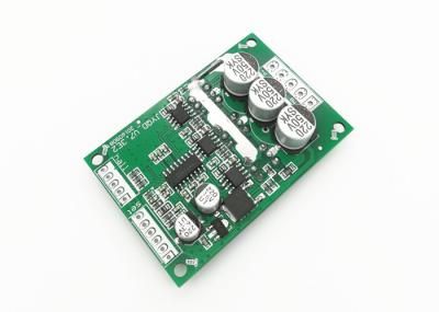
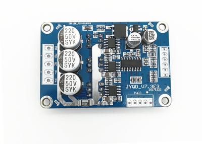
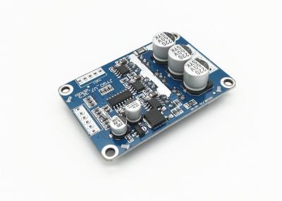
JUYI Rectangle 3 Phases 12V 24V 36V Hall Sensor Good Quality Motor Driver bldc Motor Controller with Technical Support JYQD-V7.3E2

1.Confirm the voltage and power parameters of the motor, which should not exceed the range specified for this drive board.
2.
It
is
applicable
to
120
-
degree
Hall
-
equipped
DC
brushless
motors.
Note
that
the
winding
sequences
of
motors
from
different
manufacturers do not always correspond one - to - one with those of the drive board. Customers can adjust the Hall winding
sequence or the three - phase winding sequence of the motor according to the actual situation to achieve the optimal driving effect .
3.
The
JYQD_V7.3E2
drive
board
is
a
bare
board.
For
motors
with
a
power
below
100W,
forced
heat
dissipation
is
not
required,
but normal ventilation must be ensured.
4.
The
5V
output
port
on
the
drive
board
is
prohibited
from
being
connected
to
external
electrical
equipment.
It
is
only
suitable
for
connecting external potentiometers and switches on this board for speed regulation and reversing.
5.
The
Signa
on
the
JYQD_V7.3E2
drive
board
is
the
motor
speed
pulse
output
signal,
with
an
output
current
of
less
than
5mA.

Diagram without Heatsink Diagram with Heatsink
Wiring Diagram

1.
Hall
Port
(Upper
Left)
●
GND:
Negative
interface
for
Hall
signal.
●
Hc:
Hall
signal
Hc.
●
Hb:
Hall
signal
Hb.
●
Ha:
Hall
signal
Ha.
●
5V:
Positive
interface
for
Hall
signal.
2.
Control
Port
(Lower
Left)
●
GND:
Internal
control
ground
of
the
drive
board.
●
VR:
Speed
control
port.
Analog
voltage
speed
regulation
ranges
from
0V
-
5V,
with
linear
speed
regulation
from
low
to
high.
For
PWM
speed
regulation,
it
needs
to
share
the
same
ground
as
the
drive
board.
●
Z/F:
Forward
-
reverse
control
port.
Connecting
to
5V
or
leaving
it
floating
makes
it
rotate
in
one
direction,
and
connecting
to
GND
makes
it
rotate
in
the
other
direction.
●
Signal:
Motor
speed
pulse
signal
output
port,
5V
pulse
signal.
●
EL:
Enable
control.
Connect
to
5V
to
allow
operation,
and
connect
to
GND
to
prohibit
operation.
●
5V:
The
5V
output
inside
the
control
board
is
only
for
powering
potentiometers
and
for
switch
-
based
speed
regulation
and
direction
change.
3.
Power
Port
(Right)
●
VCC:
Positive
terminal
of
the
DC
power
supply
(+).
●
GND:
Negative
terminal
of
the
DC
power
supply
(-).
●
MC:
One
of
the
three
-
phase
lines
of
the
motor.
●
MB:
One
of
the
three
-
phase
lines
of
the
motor.
●
MA:
One
of
the
three
-
phase
lines
of
the
motor.
4.
Note
that
the
motor
phase
lines
and
Hall
lines
should
not
be
too
long,
as
overly
long
wires
can
cause
signal
interference
problems.
5.
For
the
control
port,
the
port
pitch
is
2.54mm.
For
the
power
port,
the
port
pitch
is
3.96mm.
6. When adding heat sinks or installing, pay attention to the insulation of the power transistors on the drive board.
Dimension Diagram