| Price | USD9.99-99.99/PCS |
| MOQ | 1PCS |
| Delivery Time | 8-9 working days |
| Brand | Bicheng |
| Place of Origin | CHINA |
| Certification | UL, ISO9001, IATF16949 |
| Packaging Details | Vacuum bags+Cartons |
| Payment Terms | T/T |
| Supply Ability | 5000PCS per month |
| Copper weight | 1oz (1.4 mils) outer layers | Place of Origin | CHINA |
| PCB thickness | 3mm | Packaging Details | Vacuum bags+Cartons |
| Material | RO3210 and RO3003 | PCB size | 62.8mm x 62.8 mm=1PCS, +/- 0.15mm |
| Supply Ability | 5000PCS per month | Certification | UL, ISO9001, IATF16949 |
| Brand Name | Bicheng | Payment Terms | T/T |
| Layer count | 3-layer | Surface finish | Immersion Tin |
| Price | USD9.99-99.99/PCS | Delivery Time | 8-9 working days |
| Minimum Order Quantity | 1PCS |
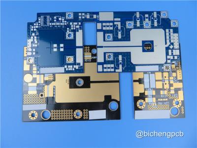
Introducing our newly shipped hybrid printed circuit board (PCB), designed for high-frequency applications with unmatched performance and reliability. This advanced PCB combines Rogers’ RO3210 and RO3003 materials, providing a unique blend of mechanical stability and excellent electrical characteristics, making it ideal for a wide range of demanding applications.
Key Features
RO3210
Material
-
Dielectric
Constant
(Dk):
10.2
±
0.5
-
Dissipation
Factor:
0.0027
at
10
GHz
-
Thermal
Stability:
-
Coefficient
of
Thermal
Expansion
(CTE):
-
X
&
Y
axes:
13
ppm/°C
-
Z
axis:
34
ppm/°C
-
Decomposition
Temperature
(Td):
500
°C
-
Thermal
Conductivity:
0.81
W/mK
-
Flammability
Rating:
V0
(UL
94
standard)
| RO3210 Typical Value | |||||
| Property | RO3210 | Direction | Units | Condition | Test Method |
| Dielectric Constant,εProcess | 10.2±0.5 | Z | 10 GHz 23℃ | IPC-TM-650 2.5.5.5 Clamped Stripline | |
| Dielectric Constant,εDesign | 10.8 | Z | 8GHz to 40 GHz | Differential Phase Length Method | |
| Dissipation Factor,tanδ | 0.0027 | Z | 10 GHz 23℃ | IPC-TM-650 2.5.5.5 | |
| Thermal Coefficient of ε | -459 | Z | ppm/℃ | 10 GHz 0℃to 100℃ | IPC-TM-650 2.5.5.5 |
| Dimensional Stability | 0.8 | X, Y | mm/m | COND A | ASTM D257 |
| Volume Resistivity | 103 | MΩ.cm | COND A | IPC 2.5.17.1 | |
| Surface Resistivity | 103 | MΩ | COND A | IPC 2.5.17.1 | |
| Tensile Modulus |
579 517 |
MD CMD |
kpsi | 23℃ | ASTM D 638 |
| Water Absorption | <0.1 | - | % | D24/23 | IPC-TM-650 2.6.2.1 |
| Specific Heat | 0.79 | j/g/k | Calculated | ||
| Thermal Conductivity | 0.81 | W/M/K | 80℃ | ASTM C518 | |
|
Coefficient
of
Thermal
Expansion (-55 to 288℃) |
13 34 |
X,Y Z |
ppm/℃ | 23℃/50% RH | IPC-TM-650 2.4.4.1 |
| Td | 500 | ℃ | TGA | ASTM D3850 | |
| Density | 3 | gm/cm3 | |||
| Copper Peel Stength | 11 | pli | 1oz,EDC After Solder Float | IPC-TM 2.4.8 | |
| Flammability | V-0 | UL 94 | |||
| Lead-free Process Compatible | Yes | ||||
RO3003
Material
-
Dielectric
Constant
(Dk):
3
±
0.04
at
10
GHz/23°C
-
Dissipation
Factor:
0.001
at
10
GHz/23°C
-
Thermal
Stability:
-
Td:
>
500
°C
-
Coefficient
of
Thermal
Expansion:
-
X
axis:
17
ppm/°C
-
Y
axis:
16
ppm/°C
-
Z
axis:
25
ppm/°C
-
Moisture
Absorption:
0.04%
-
Thermal
Conductivity:
0.5
W/mK
| RO3003 Typical Value | |||||
| Property | RO3003 | Direction | Units | Condition | Test Method |
| Dielectric Constant,εProcess | 3.0±0.04 | Z | 10 GHz/23℃ | IPC-TM-650 2.5.5.5 Clamped Stripline | |
| Dielectric Constant,εDesign | 3 | Z | 8GHz to 40 GHz | Differential Phase Length Method | |
| Dissipation Factor,tanδ | 0.001 | Z | 10 GHz/23℃ | IPC-TM-650 2.5.5.5 | |
| Thermal Coefficient of ε | -3 | Z | ppm/℃ | 10 GHz -50℃to 150℃ | IPC-TM-650 2.5.5.5 |
| Dimensional Stability |
0.06 0.07 |
X Y |
mm/m | COND A | IPC-TM-650 2.2.4 |
| Volume Resistivity | 107 | MΩ.cm | COND A | IPC 2.5.17.1 | |
| Surface Resistivity | 107 | MΩ | COND A | IPC 2.5.17.1 | |
| Tensile Modulus |
930 823 |
X Y |
MPa | 23℃ | ASTM D 638 |
| Moisture Absorption | 0.04 | % | D48/50 | IPC-TM-650 2.6.2.1 | |
| Specific Heat | 0.9 | j/g/k | Calculated | ||
| Thermal Conductivity | 0.5 | W/M/K | 50℃ | ASTM D 5470 | |
|
Coefficient
of
Thermal
Expansion (-55 to 288℃) |
17 16 25 |
X Y Z |
ppm/℃ | 23℃/50% RH | IPC-TM-650 2.4.4.1 |
| Td | 500 | ℃ TGA | ASTM D 3850 | ||
| Density | 2.1 | gm/cm3 | 23℃ | ASTM D 792 | |
| Copper Peel Stength | 12.7 | Ib/in. | 1oz,EDC After Solder Float | IPC-TM 2.4.8 | |
| Flammability | V-0 | UL 94 | |||
| Lead-free Process Compatible | Yes | ||||
PCB Specifications
-
Stackup:
3-layer
rigid
PCB
-
Copper
Layer
1:
35
μm
-
Rogers
RO3003
Core:
1.524
mm
(60
mil)
-
RO4450F
Bondply:
0.101
mm
(4
mil)
-
Rogers
RO3210
Core:
1.27
mm
(50
mil)
-
Copper
Layer
1:
35
μm
-
Dimensions:
62.8
mm
x
62.8
mm
±
0.15
mm
-
Finished
Board
Thickness:
3.0
mm
-
Finished
Copper
Weight:
1
oz
(1.4
mils)
on
outer
layers
-
Minimum
Trace/Space:
7/9
mils
-
Minimum
Hole
Size:
0.4
mm
-
Via
Plating
Thickness:
20
μm
-
Surface
Finish:
Immersion
Tin
-
Electrical
Testing:
100%
electrical
test
prior
to
shipment

Application Areas
This hybrid PCB is tailored for various high-performance applications, including:
-
Automotive
Technologies:
Collision
avoidance
systems
and
global
positioning
satellite
antennas
-
Telecommunications:
Wireless
systems,
microstrip
patch
antennas,
and
direct
broadcast
satellites
-
Remote
Monitoring:
Datalink
on
cable
systems
and
remote
meter
readers
-
Infrastructure
Solutions:
Power
backplanes,
LMDS,
wireless
broadband,
and
base
station
infrastructure
Quality Assurance
Manufactured to IPC-Class 2 standards, this PCB ensures high reliability and performance. The artwork is provided in Gerber RS-274-X format, making it compatible with standard PCB design tools.
Global Availability
Our hybrid PCB is available for worldwide shipping, allowing you to leverage cutting-edge technology in your projects, no matter your location.