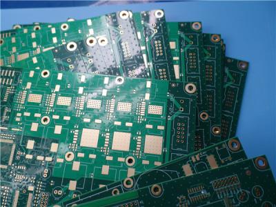
Multilayer
PCB
24
Layer
Printed
Circuit
Board
Built
On
High
Temperature
FR-4
With
50
Ohm
/
100
Ohm
Impedance
for
Industrial controls
General
description
This
is
a
type
of
high
multilayer
PCB
built
on
FR-4
substrate
with
Tg
170°C
for
the
application
of
Industrial
controls
with
24
layer
copper
track.
It's
3.7
mm
thick
with
white
silkscreen(Taiyo)
on
green
solder
mask
(Taiyo)
and
immersion
gold
on
pads.
This
is
also
an
impedance
controlled
PCB
with
single-end
impedance
of
50
ohm
and
differential
impedance
of
100
ohm.
The
base
material
is
from
ITEQ
supplying
single
up
PCB.
They're
fabricated
per
IPC
6012
Class
2
using
supplied
Gerber
data.
Each
10
panels
are
packed
for
shipment.
Features
and
benifits
Excellent
thermal
reliability
and
CAF
resistance
providing
long-term
reliability
for
industrial
and
automobile
application.
Long
storage
time
(
It
can
be
stored
for
more
than
1
year
in
vacuum
bag)
The
signal
lines
form
a
constant
low
impedance
to
the
ground
Micro-section
and
thermal
stress
test
16000
square
meter
workshop
Small
quantity
order
is
accepted
ISO9001,
ISO14001,
IATF16949,
UL
Certified
We
can
find
its
Applications
in transmitter, GSM
Modem, 3G
WiFi
Router,
phase
Shifter, embedded
Controller,
hard
drives.
![]()
Printed
Circuit
Board
Capability
2020
|
Parameter
|
Value
|
|
Layer
Counts
|
1-32
|
|
Substrate
Material
|
FR-4(including
High
Tg
170,
High
CTI>600V);
Aluminum
based;
Copper
based;
Rogers
RO4350B,
RO4003C,
RO3003,
RO3006,
RO3010,
RO3210
etc.;
Rogers
RT/duroid
5880,
RT/duroid
5870,
RT/duroid
6002,
RT/duroid
6010
etc..;
Taconic
TLX-8,
TLY-5,
RF-35TC,
TLF-35
etc..;
Arlon
AD450,
AD600
etc;
PTFE
F4B
DK2.2,
DK2.65
etc..;
Polyimide
and
PET.
|
|
Maximum
Size
|
Flying
test:
900*600mm,
Fixture
test
460*380mm,
No
test
1100*600mm
|
|
Board
Outline
Tolerance
|
±0.0059"
(0.15mm)
|
|
PCB
Thickness
|
0.0157"
-
0.3937"
(0.40mm--10.00mm)
|
|
Thickness
Tolerance(T≥0.8mm)
|
±8%
|
|
Thickness
Tolerance(t<0.8mm)
|
±10%
|
|
Insulation
Layer
Thickness
|
0.00295"
-
0.1969"
(0.075mm--5.00mm)
|
|
Minimum
Track
|
0.003"
(0.075mm)
|
|
Minimum
Space
|
0.003"
(0.075mm)
|
|
Outer
Copper
Thickness
|
35µm--420µm
(1oz-12oz)
|
|
Inner
Copper
Thickness
|
17µm--420µm
(0.5oz
-
12oz)
|
|
Drill
Hole(Mechanical)
|
0.0059"
-
0.25"
(0.15mm--6.35mm)
|
|
Finished
Hole(Mechanical)
|
0.0039"-0.248"
(0.10mm--6.30mm)
|
|
DiameterTolerance(Mechanical)
|
0.00295"
(0.075mm)
|
|
Registration
(Mechanical)
|
0.00197"
(0.05mm)
|
|
Aspect
Ratio
|
12:1
|
|
Solder
Mask
Type
|
LPI
|
|
Min
Soldermask
Bridge
|
0.00315"
(0.08mm)
|
|
Min
Soldermask
Clearance
|
0.00197"
(0.05mm)
|
|
Plug
via
Diameter
|
0.0098"
-
0.0236"
(0.25mm--0.60mm)
|
|
Impedance
Control
Tolerance
|
±10%
|
|
Surface
Finish
|
HASL,HASL
LF,ENIG,Imm
Tin,Imm
Ag,
OSP,
Gold
Finger
|
![]()
Parameter
and
data
sheet
|
PCB
SIZE
|
400
x
212mm=1PCS
|
|
BOARD
TYPE
|
Multilayer
PCB
|
|
Number
of
Layers
|
24
Layers
|
|
Surface
Mount
Components
|
YES
|
|
Through
Hole
Components
|
YES
|
|
LAYER
STACKUP
|
TOP
LAYER
0.018mm+plating
Layer
1
|
|
Prepreg
0.1016mm
|
|
PLANE
1
---
0.035mm
Layer
2
|
|
CORE
FR4
0.1016mm
|
|
GROUND
1
---
0.035mm
Layer
3
|
|
Prepreg
0.127mm
|
|
SIGNAL
1
---
0.018mm
|
|
CORE
FR4
0.1524mm
|
|
PLANE
2
---
0.035mm
|
|
Prepreg
0.1016mm
|
|
GROUND
2
---
0.035mm
|
|
CORE
FR4
0.127mm
|
|
SIGNAL
2
---
0.018mm
|
|
Prepreg
0.1524mm
|
|
PLANE
3
---
0.035mm
|
|
CORE
FR4
0.1016mm
|
|
PLANE,GROUND
7
---
0.035mm
|
|
Prepreg
0.127mm
|
|
SIGNAL
3
---
0.018mm
|
|
CORE
FR-4
0.1524mm
|
|
GROUND
3
---
0.035mm
|
|
Prepreg
0.127mm
|
|
SIGNAL
4
---
0.018mm
|
|
CORE
FR4
0.1524mm
|
|
PLANE
4
---
0.035mm
|
|
Prepreg
0.1016mm
|
|
GROUND
4
---
0.035mm
|
|
CORE
FR4
0.1016mm
|
|
SIGNAL
5
---
0.018mm
|
|
Prepreg
0.1524mm
|
|
SIGNAL
6
---
0.018mm
|
|
CORE
FR4
0.1016mm
|
|
PLANE
5
---
0.035mm
|
|
Prepreg
0.1016mm
|
|
GROUND
5
---
0.035mm
|
|
CORE
FR4
0.1524mm
|
|
SIGNAL
7
---
0.018mm
|
|
Prepreg
0.127mm
|
|
PLANE
6
---
0.035mm
|
|
CORE
FR4
0.1524mm
|
|
SIGNAL
8
---
0.018mm
|
|
Prepreg
0.127mm
|
|
POWER,
RROUND
8
---
0.035mm
Layer
22
|
|
CORE
FR4
0.1016mm
|
|
GROUND
6
---
0.035mm
Layer
23
|
|
Prepreg
0.1016mm
|
|
BOTTOM
LAYER
---
0.018mm
+
plating
Layer
24
|
|
TECHNOLOGY
|
|
|
Minimum
Trace
and
Space:
|
5
mil
/
5
mil
|
|
Minimum
/
Maximum
Holes:
|
0.36
/3.2mm
|
|
Number
of
Different
Holes:
|
9
|
|
Number
of
Drill
Holes:
|
9117
|
|
Number
of
Milled
Slots:
|
0
|
|
Number
of
Internal
Cutouts:
|
0
|
|
Impedance
Control:
|
Yes,
all
of
signal
layers
of
8
copper
layers,
50
OHM
Impedance
Controlled
for
single
ended
on
5
mil
track
&
100
OHM
for
Differential
routes
on
5mil
/
8
mil
|
|
Number
of
Gold
finger:
|
0
|
|
BOARD
MATERIAL
|
|
|
Glass
Epoxy:
|
FR-4
Tg170℃,
er<5.4.IT-180,
ITEQ
Supplied
|
|
Final
foil
external:
|
1oz
|
|
Final
foil
internal:
|
1oz
|
|
Final
height
of
PCB:
|
3.7mm
±0.10%
|
|
PLATING
AND
COATING
|
|
|
Surface
Finish
|
Immersion
gold
(29.1%
)
0.05µm
over
3µm
nickel
|
|
Solder
Mask
Apply
To:
|
TOP
and
Bottom,
12micron
Minimum
|
|
Solder
Mask
Color:
|
Green,
PSR-2000
KX700G,
Taiyo
Supplied.
|
|
Solder
Mask
Type:
|
LPSM
|
|
CONTOUR/CUTTING
|
Routing
|
|
MARKING
|
|
|
Side
of
Component
Legend
|
TOP
and
Bottom.
|
|
Colour
of
Component
Legend
|
White,
S-380W,
Taiyo
Supplied.
|
|
Manufacturer
Name
or
Logo:
|
Marked
on
the
board
in
a
conductor
and
leged
FREE
AREA
|
|
VIA
|
Via
hole
filling
at
BGA
required.
|
|
FLAMIBILITY
RATING
|
UL
94-V0
Approval
MIN.
|
|
DIMENSION
TOLERANCE
|
|
|
Outline
dimension:
|
0.0059"
|
|
Board
plating:
|
0.0029"
|
|
Drill
tolerance:
|
0.002"
|
|
TEST
|
100%
Electrical
Test
prior
shipment
|
|
TYPE
OF
ARTWORK
TO
BE
SUPPLIED
|
email
file,
Gerber
RS-274-X,
PCBDOC
etc
|
|
SERVICE
AREA
|
Worldwide,
Globally.
|
![]()