| Price | Pls contact our sales to get price |
| MOQ | 100PCS |
| Delivery Time | 20 workdays |
| Brand | AMPFORT |
| Place of Origin | CHINA |
| Certification | ROHS,REACH |
| Model Number | MF75 |
| Packaging Details | Bulk pack |
| Payment Terms | Paypal,T/T |
| Supply Ability | 10000PCS PER WEEK |
| Lead thickness(H±0.1) | 1.2mm | Place of Origin | CHINA |
| Packaging Details | Bulk pack | Height (Ho max) | 110mm |
| Lead width(W±0.2) | 12mm | Model Number | MF75 |
| Supply Ability | 10000PCS PER WEEK | Certification | ROHS,REACH |
| Pitch(F±1.5) | 30mm | Name | Power NTC Thermistor 5 Ohm 40A |
| Brand Name | AMPFORT | Payment Terms | Paypal,T/T |
| Thickness(Tmax) | 46mm | Width of low lead(W1±0.2) | 8mm |
| Price | Pls contact our sales to get price | Delivery Time | 20 workdays |
| Body size | Φ40mm/Φ45mm/Φ50mm | Lead length(L±2) | 40mm |
| Minimum Order Quantity | 100PCS | Max Steady State Current | 15-90A |
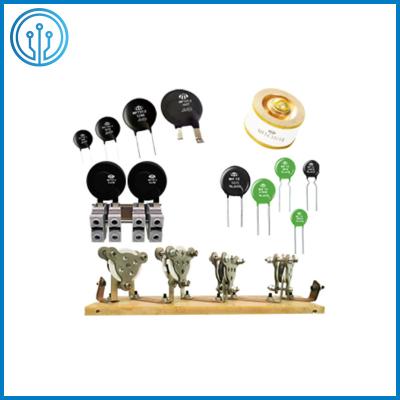
Ametherm Ampron Panasonic Alternative Power NTC Thermistor 5 Ohm 40A For Limiting Inrush Current
Overview Of The Power NTC Thermistor 5 Ohm 40A
R25(Ω):
0.2~20
Imax(A):
90A
[Product
Features]
Large
current,
long
life,
high
reliability
[Product
use]
High-power
switching
power
supply,
conversion
power
supply,
UPS
power
supply
Inrush
current
is
the
momentary
surge
of
current
created
when
power
is
turned
on
to
motors,transformers,power
suppliers
and
heating
elements.
The
more
power
required
by
industrial
equipment,the
larger
the
inrush
current.
It
can
effectively
quench
the
inrush
current
by
means
of
in
series
with
power
NTC
thermistor
in
return
circuit
of
power
supply.
The
thermistor’s
resistance
decreases
dramatically
following
the
inrush,allowing
the
steady
state
curent
to
flow
with
very
little
resistance.This
effect
provides
inrush
current
protection,
yet
allows
efficiency
during
normal
operation.The
power
NTC
Thermistor
produced
by
Dongguan
Ampfort
Electronics
Co.,Ltd.
with
large
scale,especially
MF73T,MF73,MF74,MF75
serial
products
with
big
size,which
can
be
applied
in
such
inrush
protection
with
industrial
level
as
industrial
robots
and
automation.
Features Of The Power NTC Thermistor 5 Ohm 40A
● High power, strong ability to suppress inrush current.
● The material constant (B value) is large, the residual resistance is small, and its own power consumption is small.
● Large current, long life, high reliability.
● Easy to install the circuit board, complete series and wide application range.
Application Of The Power NTC Thermistor 5 Ohm 40A
Nuclear
magnetic
resonance
equipment,
high-power
audio
power
amplifier,
high-power
toroidal
transformer.
Solar
panel
array
of
high-capacity
power
inverter.
Industrial
robot
driven
by
high
voltage
power
supply.
Dimension Of The Power NTC Thermistor 5 Ohm 40A (mm)
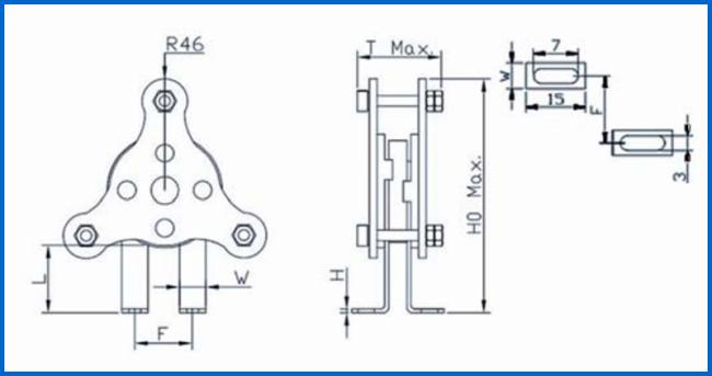
| Body size | Φ40 | Φ45 | Φ50 |
| Thickness(Tmax) | 46 | 46 | 46 |
| Pitch(F±1.5) | 30 | 30 | 30 |
| Lead length(L±2) | 40 | 40 | 40 |
| Height (Ho max) | 110 | 110 | 110 |
| Lead width(W±0.2) | 12 | 12 | 12 |
| Lead thickness(H±0.1) | 1.2 | 1.2 | 1.2 |

| Body size | Φ40 | Φ45 | Φ50 |
| Thickness | 46 | 46 | 46 |
| Pitch(F±1.5) | 30 | 30 | 30 |
| Lead length(L±2) | 40 | 40 | 40 |
| Height (Ho max) | 110 | 110 | 110 |
| Lead width(W±0.2) | 12 | 12 | 12 |
| Lead thickness(H±0.1) | 1.2 | 1.2 | 1.2 |
| Width of low lead(W1±0.2) | 8 | 8 | 8 |
Specificational Data Of The Power NTC Thermistor 5 Ohm 40A
Body diameter Φ40mm
| P/N |
R25 ±20%(Ω) |
Thermal sensitive index B±10%(K) |
Max steady state current Imax(A) | Approx R of Max current Rmax(Ω) | Max power dissipation Pmax(W) |
Dissipation factor (mW/C) |
Thermal time constant (s) | Max impulse capacitance (uF)240VAC |
| MF75-0.2/55 | 0.2 | 2600 | 55 | 0.007 | 30 | ≥55 | ≤350 | 8000 |
| MF75-0.5/50 | 0.5 | 2600 | 50 | 0.008 | 6800 | |||
| MF75-1/45 | 1 | 2600 | 45 | 0.01 | 6800 | |||
| MF75-1.5/40 | 1.5 | 2600 | 40 | 0.012 | 6800 | |||
| MF75-2/35 | 2 | 2600 | 35 | 0.014 | 6800 | |||
| MF75-2.5/33 | 2.5 | 2800 | 33 | 0.018 | 6800 | |||
| MF75-3/32 | 3 | 2800 | 32 | 0.02 | 6800 | |||
| MF75-4/30 | 4 | 2800 | 30 | 0.022 | 4700 | |||
| MF75-4.7/28 | 4.7 | 3000 | 28 | 0.023 | 4700 | |||
| MF75-5/27 | 5 | 3000 | 27 | 0.028 | 4700 | |||
| MF75-6.8/25 | 6.8 | 3000 | 25 | 0.03 | 4700 | |||
| MF75-8/22 | 8 | 3200 | 22 | 0.034 | 3300 | |||
| MF75-10/21 | 10 | 3200 | 21 | 0.038 | 3300 | |||
| MF75-12/20 | 12 | 3200 | 20 | 0.04 | 3300 | |||
| MF75-15/18 | 15 | 3200 | 18 | 0.05 | 3300 | |||
| MF75-18/16 | 18 | 3200 | 16 | 0.062 | 3300 | |||
| MF75-20/15 | 20 | 3200 | 15 | 0.075 | 3300 |
Body diameter Φ45mm
| P/N |
R25 ±20%(Ω) |
Thermal sensitive index B±10%(K) | Max steady state current Imax(A) | Approx R of Max current Rmax(Ω) | Max power dissipation Pmax(W) |
Dissipation factor (mW/C) |
Thermal time constant (s) | Max impulse capacitance (uF)240VAC |
| MF75-0.2/70 | 0.2 | 2600 | 70 | 0.006 | 45 | ≥70 | ≤480 | 11500 |
| MF75-0.5/55 | 0.5 | 2600 | 55 | 0.007 | 8000 | |||
| MF75-1/52 | 1 | 2600 | 52 | 0.009 | 8000 | |||
| MF75-1.5/50 | 1.5 | 2600 | 50 | 0.011 | 8000 | |||
| MF75-2/45 | 2 | 2600 | 45 | 0.012 | 8000 | |||
| MF75-2.5/40 | 2.5 | 2800 | 40 | 0.015 | 8000 | |||
| MF75-3/38 | 3 | 2800 | 38 | 0.018 | 8000 | |||
| MF75-4/36 | 4 | 2800 | 36 | 0.02 | 6800 | |||
| MF75-4.7/35 | 4.7 | 3000 | 35 | 0.022 | 6800 | |||
| MF75-5/35 | 5 | 3000 | 35 | 0.025 | 6800 | |||
| MF75-6.8/32 | 6.8 | 3000 | 32 | 0.028 | 6800 | |||
| MF75-8/30 | 8 | 3000 | 30 | 0.03 | 4700 | |||
| MF75-10/28 | 10 | 3200 | 28 | 0.032 | 4700 | |||
| MF75-12/25 | 12 | 3200 | 25 | 0.034 | 4700 | |||
| MF75-15/23 | 15 | 3200 | 23 | 0.042 | 4700 | |||
| MF75-18/20 | 18 | 3200 | 20 | 0.061 | 4700 | |||
| MF75-20/18 | 20 | 3200 | 18 | 0.07 | 4700 |
Body diameter Φ50mm
| P/N |
R25 ±20%(Ω) |
Thermal sensitive index B±10%(K) | Max steady state current Imax(A) | Approx R of Max current Rmax(Ω) | Max power dissipation Pmax(W) |
Dissipation factor (mW/C) |
Thermal time constant (s) | Max impulse capacitance (uF)240VAC |
| MF75-0.2/90 | 0.2 | 2600 | 90 | 0.004 | 55 | ≥90 | ≤650 | 15000 |
| MF75-0.5/65 | 0.5 | 2600 | 65 | 0.006 | 11500 | |||
| MF75-1/60 | 1 | 2600 | 60 | 0.008 | 11500 | |||
| MF75-1.5/55 | 1.5 | 2600 | 55 | 0.01 | 11500 | |||
| MF75-2/50 | 2 | 2600 | 50 | 0.011 | 11500 | |||
| MF75-2.5/46 | 2.5 | 2800 | 46 | 0.012 | 11500 | |||
| MF75-3/44 | 3 | 2800 | 44 | 0.015 | 11500 | |||
| MF75-4/42 | 4 | 2800 | 42 | 0.018 | 8000 | |||
| MF75-4.7/40 | 4.7 | 3000 | 40 | 0.021 | 9000 | |||
| MF75-5/40 | 5 | 3000 | 40 | 0.022 | 8000 | |||
| MF75-6.8/35 | 6.8 | 3200 | 35 | 0.025 | 8000 | |||
| MF75-8/32 | 8 | 3200 | 32 | 0.028 | 6800 | |||
| MF75-10/30 | 10 | 3200 | 30 | 0.03 | 6800 | |||
| MF75-12/28 | 12 | 3200 | 28 | 0.033 | 6800 | |||
| MF75-15/25 | 12 | 3200 | 25 | 0.04 | 6800 | |||
| MF75-18/22 | 18 | 3200 | 22 | 0.055 | 6800 | |||
| MF75-20/20 | 20 | 3200 | 20 | 0.065 | 6800 |
What is the detection method of NTC thermistor?
NTC
is
a
thermistor
with
a
negative
temperature
coefficient,
that
is,
the
resistance
becomes
smaller
as
the
temperature
rises
(in
an
exponential
relationship).
When
testing,
use
the
multimeter
ohm
level
(depending
on
the
nominal
resistance
value
to
determine
the
level,
generally
R×1
level),
the
specific
operation
can
be
divided
into
two
steps:
first,
the
room
temperature
test
(the
indoor
temperature
is
close
to
25℃),
and
the
alligator
clip
is
used
instead
of
the
test
pen
to
clamp.
The
actual
resistance
of
the
two
pins
of
the
PTC
thermistor
is
measured
and
compared
with
the
nominal
resistance.
The
difference
between
the
two
is
within
±2Ω,
which
is
normal.
If
the
actual
resistance
value
differs
too
much
from
the
nominal
resistance
value,
it
means
that
its
performance
is
poor
or
damaged.
Secondly,
heating
test.
On
the
basis
of
normal
temperature
test,
the
second
step
of
test—heating
test
can
be
performed.
Place
a
heat
source
(such
as
an
electric
soldering
iron)
close
to
the
thermistor
to
heat
it,
and
observe
the
universal
indicator.
Seeing
that
the
universal
indicator
changes
with
the
increase
of
temperature,
it
indicates
that
the
resistance
value
is
gradually
changing
(the
resistance
of
NTC
thermistor
with
negative
temperature
coefficient
will
become
smaller,
and
the
resistance
of
PTC
thermistor
with
positive
temperature
coefficient
will
become
larger)
,
When
the
resistance
value
changes
to
a
certain
value,
the
displayed
data
will
gradually
stabilize,
indicating
that
the
thermistor
is
normal.
If
the
resistance
value
does
not
change,
it
indicates
that
its
performance
has
deteriorated
and
cannot
be
used
continuously.
Pay
attention
to
the
following
points
when
testing:
(1)
Rt
is
measured
by
the
manufacturer
when
the
ambient
temperature
is
25℃,
so
when
measuring
Rt
with
a
multimeter,
it
should
also
be
carried
out
when
the
ambient
temperature
is
close
to
25℃
to
ensure
the
reliability
of
the
test.
(2)
The
measured
power
shall
not
exceed
the
specified
value,
so
as
to
avoid
the
measurement
error
caused
by
the
heating
effect
of
the
current.
(3)
Pay
attention
to
correct
operation.
During
the
test,
do
not
pinch
the
thermistor
body
with
your
hands
to
prevent
the
body
temperature
from
affecting
the
test.
(4)
Be
careful
not
to
put
the
heat
source
too
close
to
the
PTC
thermistor
or
directly
touch
the
thermistor
to
prevent
it
from
being
burned.